Saturday, October 26, 2013

Input to Comparator : a mod for the Doepfer A-119 and A-142


While working on what will hopefully be my next post, I was aware that I still do not have a dedicated comparator module in my system.  However, I do have several modules which contain internal comparators.  So, I decided to modify some of these to allow me access to the comparator function for use with other external signals.  

A comparator circuit is often used to derive a gate signal from a varying voltage source based on when the source exceeds a certain voltage (defined by the Threshold setting). The modules I have with internal comparators like these are the Doepfer A-119 Ext. Input/Env Follower, the A-142 VC Decay/Gate, and the A-143-1 Quad AD/LFO.  All these modules use a very similar circuit to Doepfer's A-167 Analog Comparator module.  The A-142 VC Decay/Gate (like the A-143-1), generates its Gate Out (Comparator) signal from its Env output while the A-119 generates its Gate Out from its Envelope Follower Output.

There are times when I want to use the VC Decay or Envelope Follower (or its pre-amp) but don't want to generate a Gate from their own outputs.  Instead, I'd like to use the internal comparator function with an external source.  By performing a simple modification to the A-119 and A-142, an input socket can be added to allow one to use the internal comparators with any signal (LFO, Sequencer, Min/Max, Random, etc) while still being able to use the VC Decay and Ext In/Env Follow functions separately.  Note: this mod is only described for the Doepfer A-119 and A-142, but it probably could or probably has been applied modules from other manufacturers. 


If you are already familiar with this type of socket, you can skip ahead to the videos or instructions below them.  

But, if this is your first time working with this type of socket, this might explain how it works (and other sockets with normalized connections:


You'll notice if you look at a socket on your module that the legs/pins on either side have a "normalized" connection, meaning the opposite pins are connected when NO plug is inserted into the socket.  This allows signals to be routed through the socket and interrupted with patch cables.  One leg/pin bends into an arm at 90 deg on the top of the socket and lies underneath the other side's longer arm.  I'll refer to the shorter arm as the normal arm and to the longer arm as the switched arm. Think of the socket as having a switchable input and an output for each terminal (Tip and RIng of a mono 3.5mm patch cable), and this is regardless of whether the job of the socket is a that of an Input or an Output.  Normally (when no plug is inserted into the socket), the signal at the NORMAL pin passes through to the OUTPUT, or switched pin.  But when a plug is inserted, the SWITCHED arm lifts off the normal arm, breaking the normalized connection, and instead the switched arm is only in contact with the plug's signals.

Watch these two short videos to see the Comparators reacting to external signals.  You will notice that the Env LEDs to not match the Threshold LEDs.  


A-119 "Input to Comparator" Mod from N K on Vimeo.


A-142 "Input to Comparator" Mod from N K on Vimeo.


Disclaimer:  Hang on.  Yes, this is a simple modification.  But be aware that any mods done other than by the factory will void your warranty.  Also, you should know and follow safety procedures and have well maintained equipment.  You should know how to solder.  Don't solder while in the bath.  Turn off power and remove from rack/enclosure before attempting to modify.  I cannot be held responsible for damage to your modules, burns on your fingers, spilled coffee, etc.  If you follow the instructions and look at the images, you should be fine.  I am neither an electrician nor an engineer, but I managed it.  If you're unsure, stop.  Ask a question in the comments.  If you do need to remove a PCB from the faceplate, be careful not to scratch it.  Do not touch your tools to the faceplate! It is very easy to scratch them. 


A-119 Mod:


On the A-119, the Envelope Follower signal passes through R24 (100K) to the comparator circuit.  We want to place the interrupt socket on the Env Follow side of R24, so the signal you patch in will pass through R24. 


Now rather than drill a hole in the faceplate or use a blank 4HP plate to mount my insert socket, I chose to re-purpose the 2nd Audio Out socket on the A-119 for use as my Comparator Input. You need to carefully de-solder and remove this socket from the board, or if you have extra replacement sockets, you can cut it from the board using a Dremel or wire cutters, then desolder what's left of the legs.


Next I bent the rear pins/legs of my socket up at a 90 degree angle and soldered two short pieces of wire to the pins. See Image.


Solder a 2" wire to the normal pin of the socket.  Solder another 2" wire to the switched pin of the socket.  Desolder and remove R24 from the circuit board.  Resolder the front two Ground legs of the socket to the PCB, or if you are building this mod on its own faceplate, you must connect the front two pins of the socket to Ground somewhere on the module, like the solder points for the pot brackets.  

Twist and loop together one end of R24 and the switched wire and solder together (1, 2).
I slid some shrink tube over R24 and its connection to the switched wire (3). Resolder the other end of R24 to the open through-hole on the PCB (4) and cover R24 with the shrink tube (5).  Solder the normal wire to the IC2/Pin1 junction point (6).  My wire was too heavy to get through the hole at R24, so I soldered it to some of the component legs at the same junction (6,7).  


Now the Envelope Follower signal will be sent through the socket to R24 and the comparator circuit.  Patching an external signal into the socket interrupts the internal Env Follow signal and replaces it with the external source.  


A-142 Mod:


Modifying the A-142 is a very similar process to the A-119 mod above, however the module doesn't have an "extra" socket which I can re-purpose.  Instead, I used a 4HP blank plate which I already had on hand and was already drilled to fit the Doepfer-style 3.5mm Cliff Sockets.  I threw some more sockets in the other holes and made some extra Ins and Outs.  Here's what it looks like now (left) and what it might look like if I rebuild it (right).


The resistor we want to desolder and remove is R21, located here near pin 1 of the TL084.  In this image, the signal path is travelling from right to left, so the right side of R21 is the junction of the VC Decay circuit and the comparator circuit.  We want our external signal to pass through R21. Since my 4HP expansion will be positioned on the left of the A-142 in my rack, I want to move R21 to the solder-side of the PCB, just like in the A-119 mod above.  

Basic mod:  prepare a spare socket by soldering a 2" long wire to the normal pin, another 2" long wire to the switched pin, and a 2.5" wire to the ground pins as shown here.  Twist together the end of the 
switched wire and one end of R21 and solder together.  Slide shrink tube over the switched wire.  Feed the other end of R21 through the hole in the PCB (shown left, "In to Comparator") and solder in place.  Move the shrink tube down to cover R21.  Solder the normal wire to the other solder pad (shown left, "Out from "Env Out signal") from R21's original position.  Solder the Ground wire to a GND pad on the module, pot bracket pads are good (shown left, "Ground"). Mount the socket on a blank plate.

Since I had extra holes in my plate and spare sockets, I added a few more Ins and Outs:
-  a socket is connected to the Trig In socket of the A-142 and simply acts as a multiple for the Trig In source.  
-  a socket is connected to the CV In socket and acts as a multiple for the CV In source.
-  a socket is the Comparator In socket from this mod
-  a socket is connected to the "switched" signal from the Comparator In socket.  If no patch cable is inserted into Comp In, this socket is a multiple of the A-142 Env Out.  If a patch cable is inserted, this socket is a multiple of the inserted signal. 


Thursday, August 22, 2013

An Example of Timing Multiplication with the Doepfer MAQ16/3

A few months ago, a fellow MAQ Sequencer user asked for some suggestions to spice up his sequences.  I recalled an audio/video recording I had made previously when I was experimenting with the MAQ's "Step Duration", where one sequence row affects the timing of another row (or two).  Basically, the controlling row (Row 2 in this example) is set to progress slower than the affected row (Row 1, which creates the note sequence), so that multiple Row 1 events might occur during each Row 2 event.  The value of each Row 2 step determines just how many Row 1 steps will occur.  Confused?  Follow me?

Either way, watching this video might help demonstrate.  In this video, the top row is creating a note sequence which you can hear right away and which continues through the song.  The middle row is controlling the timing of the top row.  Watching the lights, you will notice that the top row occasionally appears to speed up.  Some notes at the beginning and end of the song were muted in the recording, but you can hear the effect almost immediately. The sound being sequenced with the MAQ16/3 comes from the A-100 System, modified manually during the initial recording.  The other parts of the song were added afterwards. 


MAQ16-3 Step Duration (using t.4. on Row2) from N K on Vimeo.


Saturday, June 22, 2013

Using the Doepfer A-155 to Re-arrange Audio


   After thinking about the differences between the currently available Doepfer sequencers, I decided to try out a patch which would randomly switch between free-running beat loops using the inputs to Row 2 of the A-155, a feature unique to the A-155 in the Doepfer range.  
  
   Have a look at the video below and follow the LEDs of the top of the module.  You will notice that each step plays a different AUDIO beat loop. 


A-155 as Beat Slicer from N K on Vimeo.


about this patch....

  To make this patch, I took eight individual drum loops from old tracks of mine and loaded them into Ableton Live.  Each loop was routed to a separate mono output of my MOTU 24I/O soundcard, and from there patched directly into the sockets on the bottom of the A-155 module.  A few of the loops got some effects applied to them in Live, modulation effects like flange, so each time that beat is heard it is at a different point in the flange sweep.  What you are hearing is the CV output of the sequencer....which would normally be a set of DC voltages for controlling pitch of a VCO, etc.  But in this patch, the output is actually audio.  By patching into the lower row of sockets, you interrupt the voltage being sent to the Row 2 CV controls, which now act as volume controls for each input signal.  

  This beat-switching effect is not wave-sequencing, because each new step does not re-trigger the selected drum loop.  Instead, all of the drum loops are always playing in sync, and the sequencer is choosing which one will be heard at any given moment.  The result is similar to a DJ cross-fading between two beat-matched records, except there are eight records!  This patch is in no way restricted to beat loops, as any signals can be sequenced with this method:  different LFOs, eight more A-155s (yes!), pads, vocal tones, sound effects and drones, arpeggio loops.....

  The sequencer's audio output was processed with an A-109 Signal Processor with S+H to cutoff with some resonance with manual adjustment of the A-109 and A-199 Spring Reverb.  


Another example....

  Here's another example using the Doepfer A-155 Sequencer to manipulate audio signals.  This time I used some Jungle/DnB loops, and none of those loops were processed pre-A-155 unlike in the previous example.  I thought more "realistic" sounds might make it easier to hear the loops change.


A-155 Jungle Sequencer from N K on Vimeo.


  This patch was very similar to the first, using the same trigger pattern to control the sequencer clock and the S+H filter effect.  The A-155 has two CV outputs per row, Pre and Post, which in this case are the same signal.  Pre Out went straight to the mixer, and Post Out was split to the A-109 with S+H and an A-124 Wasp VCF with FM (fast modulation from an A-110 VCO and slower modulation from an A-145 LFO).  Both filtered versions were added to the Pre Out signal with an A-138 mixer, boosted with an A-119 Ext Input, and sent to an A-199 Spring Reverb.  Some manual adjustment of Wasp FM, A-109 Fc/Q, and Reverb Mix was made during recording.  


Saturday, April 6, 2013

Octave Cat SRM - Fixed Schematics and Layout

Original documents vs actual PCBs...

original schematic
original component  layout


The Octave Cat SRM documents you can find on the web are all the same, at least all the ones I have ever seen.  They probably all came from one source, likely Kevin Lightner's Synthfool siteThe problem though is that some of these documents (the schematics and the component layout) don't actually match the circuit boards in the SRM synthesizers that I have seen.  Nor does the schematics image match the layout image. The units I have looked at all have traces which have been cut, jumper wires intstalled, missing components, and/or extra components on the back side (solder side) of the PCB.  Not only do these models I've seen not match the documents, but they don't match one another either! 

Before I post any instructions or information on the Factory Mods that were offered by Octave Electronics, Inc., I thought it best to attempt to correct the original documents to match the actual circuit boards we have in our synthesizers.  Perhaps the corrections I show on these documents will match your own unit and save some confusion when performing the modifications, general troubleshooting/repair, or tuning.  I chose not to relabel every component on the schematic, but I got the ones that were hardest to read. 

Note:  All Cat SRMs I have looked at have some different resistor values (and in some cases, trimmer values) from the schematic and from one another.  Don't worry if your values are again different than those shown here.  

Below you will find two versions of the SRM "Board B", which is the VCF/VCA section of the synthesizer.   I haven't done this work for Board A yet.   Thank you to Tony from OakleySound for confirming that the two CV Scale circuits I drew are both viable circuit options (see pages 2 of SN:998 and SN:3866 Schematics, below).


My own SRM's Board B:

My SRM is Serial Number 998.  It has some cut traces around the Volume control and jumpers to route the control to other spots on the board.  Neither the way the board was made nor the routing change matched the documents.  Also, the CV Scale part of the VCF control circuit is different from the original documents.  The component side of SN:998 is fully populated, with the exception of there being no Temp Co resistor (R193) and that C77 (not shown on the original schematics, but does have a place on the PCB) is mounted on the solder side of the board.

The SRM SN:998 schematics, page 1:

 
click image to enlarge


The SRM SN:998 schematics, page 2:

click image to enlarge

The SRM SN:998 component layout:

click image to enlarge


Another Cat SRM's Board B, owned by Gregory Cox. 

Thanks to Gregory Cox for providing some excellent photos of his SRM SN:3866.  This unit has the same cut traces and Volume control jumpers as my board.  However, this model has no C77 installed, and is missing another unlabeled resistor.  The CV Scale circuit is again different from the schematics and different from my own unit, with resistors which are shown in the schematics mounted on the solder side of the board (as they have no place on the component side).  This SN:3866 Board B does have the Temp Co resistor included in the circuit.

The SRM SN:3866 schematics, page 1:

click image to enlarge

The SRM SN:3866 schematics, page 2:

click image to enlarge

The SRM SN:3866 component layout:

click image to enlarge


Do these match your SRM?

If you have an SRM that doesn't match either of the examples shown above, and can take some good photos, please contact me via the comment section below.  Using your photos, I can alter these files to match your Board B and add them to this page and/or email them to you.


Sunday, March 31, 2013

Octave Cat SRM - Factory Modifications


photo courtesy of G. Cox

This is the first in what will be a series of posts about modifications for the Octave Cat SRM synthesizer.  The series will cover some of the original factory mods as well as some that I've done myself.  I hope to include enough detailed information to enable anyone else to perform the mods on their Cat SRM.  


the factory mods

Here are links to the documents in which Octave Electronics described the mods that they offered:


-  Cover page
-  Mod list
-  Package price list
-  Page 1 ( Mods 1 - 6 )
-  Page 2 ( Mods 7 - 10 )
-  Page 3 ( Mods 11 - 12 )
-  Page 4 ( Mods 13 - 17 )
-  Page 5 ( Mods 18 - 19 )
-  Page 6 ( Mods 20 - 21 )
-  Page 7 (Mods 22 - 23 )


I bought my SRM from a seller on eBay sometime in 2006-2008.  It came to me having had several modifications performed at the factory over 20 years prior.  This is the only modified Cat SRM I have personally seen, and I have seen several SRMs over the years.  It came with these documents shown above, along with calibration instructions and the addendum to the user manual (five pages titled "Instruction Manual Modifiactions").  I will include these other documents in a later post.  Some of the factory mods to my SRM are NOT on the list and appear to have been specifically requested by the original owner.


my modified Cat SRM


enlarge


Shown here are several factory mods:

Output Mute, Pitchbend Range and Normal switch, Keyboard/External Control select switch, Glide On/Off switch, LFO DC-Offset switch, Keyboard or LFO to Sample + Hold Trigger In switch.


enlarge


Some more factory mods and some of my mods: 

12/24dB slope switch, HP/LP mode switch, Resonance Send/Return Loop, Noise Send/Return Loop and Routing switch


enlarge


Another factory mod and more of my own:

VCO1 Audio to VCF Mod1, VCO1 and 2 Send/Return Loops and VCF/VCA routing switches


enlarge


I added these Doepfer-style sockets at the edge of the case.  These sockets have "normal" connections, allowing a signal to run through the socket until a cable is plugged in.  The cable interrupts the normal signal and inserts the external signal. The sockets shown here are Audio and CV inputs to the VCF and VCA.  The VCF Out signal can be interrupted via the VCA In socket.  The External In sockets mix with the VCF Out instead.


enlarge
 These sockets, switches and pots are part of the factory mods, however they don't all match those listed in the documents above.  I haven't yet determined what function the Gate socket provides.  The LFO, VCO2, Interface, and Pedal inputs are all CV inputs for use with a pedal or other CV source. 
enlarge


The Pedal Input is connected to the VCF, VCO1, and Pitch switches and pots, allowing you set a mod depth for those three parameters with the pots and to have on/off control with the switches.  


Sunday, March 17, 2013

Using A-155 Seq for Evolving Drum Patterns


Trigger Sequencers:

There are a number of dedicated trigger sequencers on the market today aimed at making it easy to create drum patterns for your modular.  But, … I don’t have one.  I do, however, have some other analog sequencers that can be coaxed into creating trigger patterns which range from standard 4/4 beats to complex, evolving rhythms.  Below is one example of such a patch, focusing on the features of the Doepfer A-154/155 Sequencer and Controller combination.    


First, the audio/video example:


While enjoying the video below, pay attention to the LED indicators circled in this image.  You will be able to see how the sequencer is controlled by the LFOs, and how the indicators correspond to what you are hearing.  


Explaining the example:

The drum sounds:
I made some drum sounds with my modular for this example.  The “Kick” is made with a Doepfer A-102 Diode Filter, with the resonance set to self-oscillation.  The trigger for the kick goes to two ADSR modules, one for the VCA after the filter and one for the filter cutoff to create the drum’s percussive attack.  The “HiHat” is the closed hat sound from an Analogue Solutions HH88 module, with some Analogue Solutions SR01 Spring Reverb (original version).  The “Snare” is the digital noise output from a Doepfer A-117 Noise/808 Source module filtered by a Doepfer A-121 Multimode Filter with LFO modulation, using the BP output with some A-199 Spring Reverb.  

The A-155 analog/trigger sequencer:
Trigger routing switches
The A-155 has two rows of center-off switches used to route each step’s trigger/gate commands to any of the four trig/gate outs.  The top row of switches selects between Trig Out 1 and Trig Out 2 (or neither).  The bottom row selects between Trig Out 3 and Gate Out (or neither).  I was able to create a pattern where each step triggered a single drum sound.  Step1 is the “kick”, 2 is off, 3 and 4 trigger the “HiHat”, and 5 and 6 trigger the “snare”.   I chose to make my A-155 pattern 6 steps long, so it plays almost three cycles within a typical 16-step pattern.
 

The A-154 Sequencer Controller:
A-154 Manual and CV controls
The A-154 provides additional control of the features of the A-155, including CV control of play direction, first and last step, etc.  Using the attenuated CV inputs, I was able to use “pulse” shape LFOs to switch between two settings.   I used Doepfer A-146 LFOs because of their variable shapes.  By adjusting the rate and pulsewidth, I could control how often and for how long the settings would change.   The low swing of the LFO has no effect, so the setting is determined by the manual control value.  The high swing of the LFO changes the setting to the value set by the CV In attenuator.  One LFO switched the play direction from Forward to Random:  frequency = Rate, and duration = PW.   Another LFO switched the First Step from Step 1 to Step 5. 

larger image


These two LFOs are almost fully to the right of the middle row of modules pictured in the video example, and you can just make out the lights corresponding to the snare rolls and random fills. Both A-146 LFOs are shown circled yellow in the image to the left.  The leftmost is in its "high" state (LED is lit), and you can see that the A-155 is therefore in the Random play direction (circled orange).


Driving the A-154/155:
Ext clock and reset inputs
To control the tempo and the reset messages to the A-154/155, I used two rows of a Doepfer MAQ16/3 Sequencer.    One row outputs a constant 16th note gate pattern and this is used as the tempo.  One row outputs a single gate on the first step of the 16 step pattern which is used to reset the A-154/155 to step 1 of its pattern.  

Note:  Using the MAQ in this patch may seem like a waste of sequencer power.  However, the MAQ makes this patch able to make rhythms that are infinitely more complex than the one shown here.  The MAQ row being used as the "clock track" could have rests, could be a length other than 16 steps, and could have its own timing controlled by the third MAQ row!   You might have a 5 minute song with no 2 bars the same!


Additional noises in the example:
CV sequence row
There is a simple CV sequence which is controlling a Tiptop Z3000 VCO filtered by a LPF.  Both the VCO and the LPF receive the CV sequence.  This CV sequence is affected by the Forward/Random switching and the First Step switching of the A-154/155 in this patch.  I also layered a simple 4/4 drum pattern to give the example a base rhythm, and added a pad sound and bass sound to show how the evolving A-155 drum pattern might sound in practice.


Saturday, February 16, 2013

Octave Switching and Waveshaping with the Blacet Research VCO2100

  
the videos:

  -  Tri LFO as clock
  -  3 oct arp
  -  8on/8off sequence
  -  mostly monotone
  -  LFO shift groove
  -  Joystick control

for additional information about these patches and the Blacet VCO, see below videos

the videos...

 Example 1:
 Using a Triangle LFO as your Clock/Rhythm


Blacet 2100 VCO - +or-1 Octave Shift w Tri LFO as Clock from N K on Vimeo.

 A Triangle LFO output is patched to the +/-1 Octave input of the Blacet VCO2100.  This normal, free-running Triangle provides the tempo in this example.  Each octave shift created by the LFO is one eighth note step.  The Triangle provides equal time in all three octave ranges, as it takes the same amount of time to get from -2.5V to +2.5V as it does to get from +.2.5V to +5V and back down to +2.5V.  This means there are four shifts of equal length per triangle cycle.  See the image below or larger image.


  It would also be possible to use a synced software LFO like those available in a Doepfer MCV24 MIDI/CV-Gate Convertor.

  The changing pitches are from a free-running Doepfer A-155 Analog Sequencer set to a slow tempo (this could easily be replaced by a keyboard or quantized ribbon, etc., the sequencer is simply freeing my hands in this example).  The sequencer and Shift LFO are not in time with each other which creates “extra” notes when the sequencer advances between octave shifts, and creates a less predictable movement (the sequencer and LFO could be synced by using the Square out of the LFO to Clock In of the sequencer).

   This patch reminds me of playing with synths like the Roland SH-101/Juno 6 or Korg Polysix, which all have arpeggiators and trigger inputs to clock them.  It didn’t matter when you pressed a new key because the sync and trigger was already planned.  However, with these old machines, I don’t think you would not get the “extra” notes.


 Example 2:
 3 octave arpeggio from a 4 step sequence – Part 1

Blacet 2100 VCO - +or-1 Octave Shift - 4step 3oct Arp from N K on Vimeo.

  The Doepfer MAQ16/3 sequencer Row 1 provided a MIDI-synced 4 note sequence, timed to 16th notes.   With the Blacet VCO2100  you have voltage control over Octave Shift to cover three octaves.  By using a Ramp LFO shape from a Doepfer A-145 LFO, and resetting the cycle with a trigger message from Row 2 of the MAQ16/3, I was able to create an arpeggio that covered 3 octaves, with 4 notes per octave (of course, the MAQ can do this all by itself, but this example is to show how the VCO operates).  The MAQ16/3 CV 1 Out goes to the CV In of a Doepfer A-156 Dual Quantizer which forces the voltages into a major scale.  The A-155 sequencer’s 8 step sequence goes to the Transpose In of the Quantizer.     The LFO reset sequence needed to be 12 steps long with a trigger at Step 1 only, and could be delayed just a bit (like with an A-162 TDEL or since we are using a step sequencer, use a different step) so that the octave change occurred later. 

  This pattern was made using several modules and machines as shown in the basic patch image below.  


Example 3:   Eight 16th notes with Transpose and Shift

Based on Example 2, this time the Row 1 MAQ16/3 sequence was extended to 16 steps from 4, and Steps 1-8 have a 16th note, Steps 9-16 are Off.  The MAQ16/3 CV 1 Out goes to the CV In of a Doepfer A-156 Dual Quantizer which forces the voltages into a major scale.  The A-155 sequencer’s 8 step sequence goes to the Transpose In of the Quantizer.    The Blacet VCO Octave Shift is controlled by an A-145 LFO Ramp shape, with Reset from Row 2 of MAQ16/3 set to every ¼ note.  Another LFO (Doepfer A-146 LFO2) creates a slow, narrow pulse which modifies the decay time of a Doepfer A-142 VC Decay which in turn controls the VCA.  You may hear the notes go from short to long.


Example 4:  Mostly Monotone


Based on Example 3, I decided to insert a manual switch between the quantized 1V/Oct MAQ16/3 sequence and the Blacet 2100 VCO input.   This way the pattern could focus on the root note and the Octave Shift.  Other than that, the patch is about the same.  I switch back and forth between straight one-pitch sequence and the Octave Shift sequence so you can hear the difference.  Transposing of the one-note rhythm begins at about 4m08s.  The Octave Shift is modified by a Ramp LFO with reset.


Example 5  -  LFO Groove Shift of A-155 Pattern


Blacet 2100 VCO - +or-1 Octave Shift w LFO Groove from N K on Vimeo.

  Different day, similar patch.  The A-155 Sequencer and the A-145 LFO with Reset both get a MIDI-synced ¼ note trigger pattern.  The A-155 8-step sequence is running in Pendulum mode which plays forward and then backward repeatedly, always playing the first and last notes twice (although, you may notice that my pattern doesn't start from Step 1).  The LFO rate is adjusted manually and in real time (as in some of the other examples) creating shuffle-like, off-time rhythms.


Example 6:  Joystick Control


  Have a listen to “Take My BreathAway” (Mylo Remix) by The Knife.  It almost sounds like Mylo is changing the Octave setting of whatever synth is being used while the sequence is running.  I imagined I could do this using the Blacet VCO’s +/-1 Octave input and a bi-polar joystick like a Doepfer A-174.  If you're in a rush, skip ahead to the shift effect which begins at around 2m00s in the original version of the song.

  My version uses samples from the original, but I reprogrammed the synth line to play from my modular using the Blacet VCO2100, an A-115 Audio Divider, and with +/-1 Octave control from a joystick.  

  The joystick has a voltage offset control which can offset up or down, so you can make its output go from -7V (full negative offset) to 0V, or 0V to +7V (full positive offset), or anything in between.  If the joystick's voltage offset control is kept centered (-3.5V to +3.5V), then at the Blacet VCO's +/- Oct input, fully left = -1 Oct, centered = normal, fully right = +1 Oct.  The joystick was kept mostly left so I could add 1 or 2 octaves as I chose.


the basic patch


The patch which was the basis for these examples is shown below. Of course, the sequencers, quantizer, A-146 LFO to VC Decay, and filters are not necessary to use the Blacet VCO2100 octave shift function.   


  These examples are mainly about the +/- 1 Octave Shift feature.  This feature really appeals to me.   See, I am not really a “keyboard player”.   Although I have many keyboards, I’m not the kind of performer that you might see sit at a piano or jam with a jazz band.  My work tends to be controlled randomization to some degree.  That’s not to say that songs I’ve worked on don’t have me actually playing a lead…. but more often than not, I sequence.  Sometimes, I arpeggiate.  

  Usually if a machine has an arpeggiator, it is equipped with a variety of settings to widen the possibilities beyond just repeating a few notes.  You may be able to select whether the notes go Up, Down, Up+Down or perhaps even Random.    There is often the ability to have your notes repeat in other octaves, not just the keys you are holding (C1,D1,E1, F1,->C2,D2,E2,F2,->C3,D3,E3,F3 and then back to C1).  It is possible to do this with a combination of modules like Voltage Control Source, a Sequential Switch, analog sequencers, and the Blacet Scanner 2600  but .....

Doepfer A-174 Joystick module

.... by using a Blacet VCO2100, the task of octave shifting is handled right in the VCO itself because the switches and reference voltages are built-in.  All you need to add is a modulation source (like an LFO or Joystick) to the VCO2100 +/- Oct Input.  This enables you to control the pitch of the VCO with a keyboard or sequencer by its 1V/Oct input while controlling the "octave shift" separately via the +/- Oct input.  
As previously mentioned, the source just needs to be able to swing from below -2.5V to above +2.5V.  So, 
if you have the modules to invert, offset and amplify CV signals, there really is no limit to the control devices you can employ: sequencers, ADSR, follower, min/max, theremin ....     


How I used the LFO for Octave Shift

  To modulate the Octave Shift, I used a Doepfer A-145 LFO because of its Ramp shape (like a Sawtooth that resets to the low state) and its Reset input (restart the LFO wave at the beginning of its cycle by means of an external trigger pulse). I used both the Triangle and Ramp shapes of the A-145.  I wanted to start my patterns in the lowest octave (-1 Octave shift) by using the LFO Reset In.   The Ramp is perfect for this but the A-145 Triangle resets high (see below).   So, I used a Doepfer A-175 Dual Voltage Inverter to make the Triangle reset Low. I could have just as easily inverted the Saw of another LFO (with low-reset triangle) to make a Ramp Some triangle LFOs reset high, some low, although they almost always show a low reset shape on the control panel, sometimes drawn starting from 0V instead of -5V.
  
  Two different LFO modules, one resets high (left) and one resets low (right):

Doepfer A-145 LFO
Doepfer A-146 LFO 2
(please disregard the sloping Squares, they are not accurate examples of either LFO)


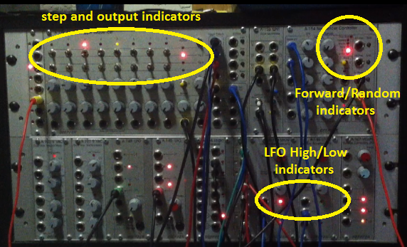
  By using Reset In and changing the LFO rate you can create complex octave shift timing. Several of my video examples show this happening.  Below is a sketch showing what your modulation shape might look like if a high-reset triangle LFO receives a 1/4 note reset signal and the LFO is faster than 1 cycle per 1/4


  Also, by delaying the Reset signal with your trigger sequence or a module like an A-162 TDEL, and/or by dividing the clock/trigger signals with a module like A-160, you can have even greater control over the timing of Octave Shift. It is possible to use a combination of clock signals, LFOs, clock divider, trigger delay, etc to interact with one another for even more options.  

  Note: with the A-145 LFO that I used, the Ramp waveform actually cycles twice for every Square cycle.  If I want to use a Ramp (LFO A) at 1 cycle per trigger, I need to use the Square out of another LFO (LFO B) as a clock/trigger source.  I split the LFO B Square out and route it to my clock/trigger destination (sequencer clock in, S+H, ADSR) and to a Clock Divider.  Then the "divide by 2" or /2 output (a clock/trigger pattern half the rate of LFO B) is routed back to the LFO A Ramp reset, creating one LFO A Ramp cycle per every two LFO B Square cycles.  See image.  


my examples

  My examples contain some percussion from an Elektron Machinedrum, reverb/delay from a TC Electronics M-one, one example contains a virtual pad sound, and the last one has samples from the song I am emulating.  All audio was recorded in one take into DAW (Nuendo) as a stereo mix and then synced to the video. I edited one or two videos just because of their length.


manual momentary and
toggle switches
  All examples have several things affecting the sequence, so I use DIY manual switches to turn functions OFF and ON to show the differences.  These changes are also captioned at appropriate moments during the videos.  The Blacet VCO is the only VCO used, sometimes two outputs mixed through different filters, but in Example 6 (and perhaps one or two others) I added a sub-octave tone from a Doepfer A-115 Audio Divider driven by the Blacet VCO2100.  


Below are some sound examples of the above features from the Blacet website:
  • Sound Sample 1: the octave switch and VC wave are controlled by another VCO's triangle and sawtooth waves.
  • Sound Sample 2: same as above with an external sequencer connected.
  • Sound Sample 3: the pulse wave, heard through a Final Filtre and the VC wave, being modulated by the FF's AD output.


The special features:
Voltage control of Waveshape 
 and +/- 1 Octave Shift

+/-1 Octave Shift

Blacet VCO2100 +/-Oct input

  The feature which is extremely unique is the Octave Switching circuit that allows the pitch to shift up or down one octave, controlled by CV input.  When the controlling signal goes below -2.5V, the pitch drops one octave. When the CV signal goes above +2.5V, the pitch shifts up one octave.   If you control this input with a -/+5V triangle LFO, you will have equal parts -1/0/+1 octave shift.  Of course, you might use other control signals like a bi-polar joystick, random generator, etc.  


  • Waveshape 

      The waveshaping circuit has its own signal outputCV input (no attenuator) and manual control.  This circuit morphs from "Triangle to Square with "Tube" Sound".  Some examples of this feature are shown below.   

      This video was sent to me by John Blacet as an example of what one should expect from the 
    2100 VC Wave output, with full sweep of the Wave range.  


    blacet 2100 VCO vc wave out from N K on Vimeo.


      My waveshape videos are not good presentations of the waveform, but they do show some shaping and have audio.  I believe the sloping square shape may be due to something in my signal path trying to correct DC Offset.  All my modular VCOs (Doepfer and Tiptop) display the same sloped shapes using this scope.  This effect is also visible in my previous post in the images and videos of the Graphic VCO shape.  Below is one video of my VCO2100 Wave output.  This video may be replaced soon. 


    Blacet VC Wave from N K on Vimeo.


    The standard features…

      It has all the features one might expect: 1V/Oct CV inputs (no attenuators), Coarse and Fine Tune controls, outputs for Saw, Triangle, Sine and Pulse waveforms, Pulse Width control, PWM input (no attenuator), a selectable Exponential/Linear FM input with level control, and a Sync input. In addition, the Blacet VCO2100 also has some interesting features that are not found on many, or perhaps any, modular oscillators available today. 

                                                                                   from the VCO2100 manual


      a quick look at its roots


     Blacet Research is a manufacturer of modular synth modules based in Oregon, USA. They have a range of modules available that cover what one needs to make a functioning synthesizer both as factory-built units and as DIY kits (VCO, VCF, VCA, EG, LFO, etc), plus some more uncommon ones like Improbabilty Drive, Binary Zone and Hex Zone. The modules are FrakRack format and require a +/-15V power supply.

      Below is a post I found online which discusses the history of the VCO circuit that John Blacet adapted and built upon to make the VCO2100:
       
      “Terry Michael …… contributed a significant number of the core circuits published in I Electronotes magazine.

      In particular, Terry perfected and published the "Classic Sawtooth Engine".  Terry’s sawtooth reset design (EN#62 Pg. 14 Feb. 1976) is the most widely copied.  This design was picked up from Electronotes magazine by the engineers at Moog Music Inc. and others. The design forms the basis for the VCOs used in the Micromoog, Source, Prodigy and the other small Moog synths.


      No money or acknowledgment was ever paid Terry for the design, as it was not legally required.


      Terry continued to improve the design over the next 25 years, and I connected John Blacet with Terry Michael's updated and improved sawtooth engine. This design is technically superior to the VCOs used in the Moogs and all other copies of Terry's older design.


      John Blacet kept the important parts of Terry's new design and they appear in the Blacet VCO!


      The Blacet VCO is the only commercial version of Terry Michaels "Improved Sawtooth Engine" (remember the old inferior version sold something like 50,000 copies).


      The Blacet VCO is the ONLY version of the "Sawtooth Engine" officially licensed from the originator of the design.”


      Best Regards,


      Grant Richter

      Wiard Synthesizers

    See link for full text


    via email:
      The novel (designed by me) parts of the VCO are: the VC Wave and the Oct Switch function - John Blacet