
Thanks and credit to the MIDIbox originator, Thorsten Klose, aka TK... and I applaud his continued development and support via the MIDIbox Forum! Additional thanks to forum members Mongrol, Hawkeye, Latigid On, Slo, Seppoman, and others for their inspirational build-guides, answered questions, and trouble-shooting help...and thanks to Sean Pendleton for laser-cut wood prototype and Andrew Scheidler for demo videos.
Disclaimer: I am in no way affiliated with MIDIBOX.ORG, and I do NOT profess to know all there is to know about the MIDIBox Hardware Platform. I do not profit from any information contained on this site, nor the purchase of PCBs, enclosures, parts kits, or anything else discussed in this post. To the best of my knowledge, all the information contained herein is accurate. My own SeqV4 is almost complete, and this page will be updated as I make progress. Email questions, comments, and corrections to nirokeforums@gmail.com
This is a DIY project. If DIY is not for you, join the MIDIBox Forum (find link below), visit the Flea-Market, and find a pre-built unit for sale that will fit your needs.
- Updated 17 July 2017 - added female IDC connectors to relevant parts lists and added link to connections diagram in Line Driver section
- Updated 23 July 2017 - changed electrolytic capacitors in AOUT_NG kit to better fit layout and lead spacing
- Updated 08 August 2017 - MODULAR ADDICT NEW SOURCE FOR MIDIBOX PCBS INCLUDING CS BOARD PCBS!!! SEE BELOW.... plus a suggestion added to Core Board build if adding a Quad_IIc_MIDI board
- Updated 02 October 2017 - Modular Addict now also carries "Waldorf" knobs and data wheel (see below), and I've added notes to the CS Board section with regards to bottom-mounting the Data Encoder
- Updated 02 December 2017 - removed links to MIDIbox Shop boards and kits :( Added some thanks and credits at the top :) Other general edits, info about costs, etc
- Updated 10 December 2017 - kind of a lot. Formatting, images, updated some project files, progress updates and additional info
- Updated 30 December 2017 - decided a few weeks ago to add the TPD module to my build... some info below

What IS this thing ?
The MIDIbox SEQv4 is a "16 Track Live/Step/Morph Sequencer and Advanced Arpeggiator", and frankly, the most powerful music sequencer I have ever owned or used. Its list of features is dizzying, and its results are immediate.
Each of the 16 tracks, and every type of track...
- NOTE (polyphonic)
- CHORD (plays one of 37 pre-defined chords)
- MIDI CC (like a note track, but layers are not pre-assigned to note on/off)
- DRUM (up to 16 drum voices per track)
... has its own settings (clock, length, direction, rotation, LFO, groove, scale, etc) ... has up to 16 parameter layers (note, velocity, bend, CC, probability, delay, aftertouch, etc) ... has up to 8 trigger layers (gate, accent, glide on/off, roll, random value, etc) ... and is fully editable while running.
 |
| Group, Track, and Layer Select buttons |
While the tracks are grouped in fours (track 5 is actually called G2T1, or Group 2/Track 1) they remain independent, but they can also be made to interact with one another (one transposes another, one advances another, etc), or be fed by one of up to 4 MIDI inputs. Not only does the SEQv4 have the most flexible, powerful, and interactive step-sequencing I've used, it also has "live sequencing" (Jam Mode) where you can play in and overdub MIDI data which will begin to play back as soon as the track loops. Morphing allows you to smoothly change between two parts of the same track, adjusting the first and last steps of a looped section. The arpeggiator is programmable (settings per note) and can be further modified by all the same parameters that the Step and Live-recorded tracks get to play with, and it can be applied to an existing track or to any of the MIDI inputs in realtime. Sequence data can be output via MIDI ports, USB MIDI, OSC (ethernet), or CV/Gate. All that said, this summary still doesn't do it justice.
(for some example videos of what the SEQv4 can do, scroll to the bottom of the page)
Building my MIDIBox Seq v4 required a bit of research….
All the information you will need is available on the internet, but it
can be confusing and overwhelming when you first approach the project,
especially as there is no ONE WAY to build it.
“MIDIBox" (or MBHP) is actually the name of the hardware platform developed by Thorsten Klose (there are several MIDIbox-based synthesizers, controllers, and drum machines, etc in addition to this sequencer), “SeqV4” is the
name of the application that gets loaded on to your finished hardware to make it a sequencer, and there are many possible hardware configurations
and parts selections available so every device can be uniquely customized. With that in mind, the goal of this guide is not to examine every
possible option, but to simply help others get a head start if they are
considering building a MIDIBox SeqV4, whether that be a minimal, midi step
sequencer or one like mine which has a few more options. I do not intend to create guides for any
peripherals which I have not built (and tested) myself. This document compiles relevant links and
information from multiple sites in an effort to make it easier to understand
and navigate the process of designing and building your own MIDIBox SeqV4.
The main page for everything
MIDIBox related is http://www.uCApps.de/. Admittedly, this page can be an information overload if you are just starting your build, but almost everything you
need to know (and a ton more) is on this site.
Much of what I am doing in this write-up is taking links from the uCApps site (and
a few others like http://midiboxshop.bigcartel.com/info) that are relevant to building my Seq V4 and introducing
them in a way that might have made more immediate sense to me when I started my
build. Also check out http://wiki.midibox.org/
What Do I Need ?
To put it simply, you need a set of PCBs, a bunch of parts, something to put them in, and a way to teach it.
Anyone building a Seq V4 will need at the least:
-
a “Core” module…. This is the center of the
MBHP, or MIDIBox Hardware Platform, which hosts the CPU board (purchased
separately) and links to all the optional peripherals.
-
a CPU (referred to often as the “discovery
board” or by the model number, like STM32f4)
-
a MIDI IN and/or OUT interface (most likely, and
often more than one)
-
a control surface (Wilba’s CS, the future V4+,
or DIY)
- two 40x2 displays
-
a case or front panel and relevant hardware
-
USB cables and SD Card (the SeqV4 can be powered via USB, but cables are also needed for programming and firmware)
-
a computer running freeware to flash and update
MIOS (MIDIBox operating system)
- ribbon cable, soldering equipment and various tools
You, like me, may opt to include other peripherals:
-
an analog output board for CV outputs
-
a
“digital” output board for gates, clocks, triggers, etc.
-
a set of
boards to transmit and receive signals from the MIDIBox enclosure to a breakout
box or panel
- external power supply
- TPD : Track position display, tempo display and control knob, step count display, four assignable buttons
And you may choose to add other options which I have not
built:
- 4-16x16 X0X-style button array (Button/LED Matrix, or BLM)
-
And more….see the left-hand column on http://www.uCApps.de/ under “MB Hardware
Platform”…but keep in mind that not all peripherals are necessary with every
Core variant
 My build includes the
following:
My build includes the
following:
-
STM32F4 based Core with STM32F407G* Discovery
Board CPU
* it is essential that your discovery board have the suffix 07G!
-
ST-Link, MIOS32, and SEQ v4.094 software (or latest version)
- Wilba CS Board
-
MIDI I/O module (x2)
-
Quad IIc_MIDI module
-
DOUT digital output module
-
AOUT_NG analog output module
-
Line Driver transmit and receive module
-
LCDs
- Laser cut case for SEQv4 (modified design based on
the Mongbox)
- Laser cut case for Breakout Box with custom output PCBs
- Internal 5V regulator,
power receptacle, power switch
- TPD Module in yet another laser cut case...
PCBs :
ModularAddict.com has started stocking a near full range of MBHP pcbs! All board prices mentioned below will be based on their prices. However, you may need to have some (like the Line Driver Tx and Rx boards used to boost signals sent to an optional breakout unit for CV/Gate, etc) fabricated at a PCB manufacturer like OSH Park (https://oshpark.com/), or you may be lucky enough to find someone on the MIDIBox Forum (http://midibox.org/forums/) who has a few extra to off-load. The TPD board is, as far as I'm aware, only available via the MIDIbox Forum. You could always make your own circuit boards if you are inclined and determined as schematics are available for each board! Some older boards are still available at Mike's Midishop (http://www.mikes-elektronikseite.de/mshop_englisch/index.htm), but I didn't have a use for these in my build.
Note: to build my SEQv4 using Modular Addict boards would cost $88 for the PCBs and would include the data wheel knob (plus shipping, would not include Line Driver boards, TPD board, or my custom boards). I probably paid another $60+ for that set of PCBs from MIDIBox Shop when I built mine simply because I did not order them all at once and paid for shipping repeatedly, so it makes sense to plan ahead and order once. To build a bare-bones SEQv4 (2midiIN/2midiOut only), your PCBs would cost just $56 plus shipping (includes CS board, STM32Core, MIDI I/O, and data wheel knob).
Parts Kits :
I have links to Project Files at Mouser for each of the modules I've built (except for the TPD) which will save you from finding all the parts you need yourself. Any price quoted on these pages are subject to change but accurate at time of writing.
(Mouser has several ways to save lists of parts for different projects: BOM, shared carts, project files, etc, but I will me using the Project File level. These allow you to load a project, click "order project" to send those parts to a cart, then load another project to purchase more in the same order. Sharing BOM would still require you to select individual parts, and sharing carts makes it difficult to purchase more than one project in one order. So if I use the term Project File or Kit, I am referring to the Project File level of saved files in my Mouser account. I don't profit in any way by you using these kits.)
Of course, some parts may be unavailable or out of stock at Mouser, cheaper from other distributors, or not the highest quality available, so if you want to shop around, you will at least have the specs about each part in my project file. For example, the Switchcraft brand midi sockets in my Mouser carts are $2.93 each, but you can get CUI,Inc. brand midi sockets from Digi-Key for $1.02 each. As my build uses 12 sockets, that's a difference of $22.91, but you'll want to compare the savings you will get to the cost of additional shipping fees. Obviously it made sense for me to place two orders from different distributors, but for the sake of simplicity, I have created carts that source all parts from a single distributor (per MBHP module). Honestly, Digi-Key has better prices on DIN (midi) connectors and IDC headers/connectors, so if you are on a tight budget, it may be worth the effort to make a list of these parts from each module of your planned build, remove them from the Mouser Project Files, and order them all at one time from Digi-Key. Reichelt in Germany has better prices than ANY of the US options, but I have not ordered anything from them (....yet...perhaps for my next build!) In some cases, it is cheaper to buy more of something than it is to buy just the required quantity, so you may end up with extra parts if you use my Mouser parts kits.
There are some parts that are customizable in the sense that you might want a specific knob style, LCD color combination (or even OLED or VFD), LED shape, etc., so keep this in mind when reviewing my BOMs or project files and when deciding on a front panel or enclosure design (**my build uses rectangular LEDs, but my kits contain the more common round LEDs instead**). Check the forum for a post about a new Seq V4+ control surface PCB, panel, and software before committing to a case, panel, or control surface (CS) board.
Programming :
Really most of the programming has been done for you already, you just have to transfer the data to the STM32F4 to set up the platform and the sequencer application, create a couple folders on the SD Card, and then if necessary, edit the hardware configuration file (MBSEQ_HW.V4) that is stored on the SD Card. I had to edit mine (Wilba version) to assign duties to the DOUT module's outputs and setup my TPD, but that's all, if I remember correctly. See "OS Links" at the bottom of the STM32F4 Core section below.
The SEQv4 Modules I've Built ....
STM32F4 Core
I chose
to use the STM32F4 Core mainly for its
availability, although it seemed like the best choice at the time of writing. An
STM32F407G Discovery Board (the CPU) mounts to the Core PCB and is programmed
using freeware (this is much easier than it might sound). Be sure to purchase the 07G version of the STM32F4!
 At time
of writing, the Board alone is $9.99. My
MBHP_Core_STM32F4 project file at Mouser totals about $52 plus shipping,
includes all parts from the Shop’s Kit plus
the STM32F407G Discovery Board ($19+) and 5’ of 16-conductor ribbon cable, but some
parts may not be ROHS compliant. Some
parts in my kit are currently cheaper from other distributors: the IC sockets,
shrouded IDE headers, and 2x25 female headers. However, these item can be added to a future order, you don't need them to build the Core.
At time
of writing, the Board alone is $9.99. My
MBHP_Core_STM32F4 project file at Mouser totals about $52 plus shipping,
includes all parts from the Shop’s Kit plus
the STM32F407G Discovery Board ($19+) and 5’ of 16-conductor ribbon cable, but some
parts may not be ROHS compliant. Some
parts in my kit are currently cheaper from other distributors: the IC sockets,
shrouded IDE headers, and 2x25 female headers. However, these item can be added to a future order, you don't need them to build the Core.
Note: It is not necessary to purchase and install all the shrouded headers. For example, if you know that you only ever want to have a bare-bones SEQv4 (CS and MIDI I/O), then you only need to include 4 of the 12 shrouded headers
My Mouser cart doesn't contain the
required SD card (2GB) or USB cables as they are far too expensive when sourced from
distributors like Mouser. The cables can
probably be purchased locally (if you don't already have some from a phone, camera, game device, etc), and the SD card from eBay or Amazon.
Diagrams of connections and assembly/programming instructions are available on the
main page for the STM32f4 Core, scroll down to the relevant section:
 http://www.ucapps.de/mbhp_core_stm32f4.html
Note the need to update firmware on discovery boards marked with MB997D.
The discovery board can be programmed before
the Core Module is built. The bootloader and application software current at time of writing is also linked below. Once your Core is built and the discovery board is coupled to it, you may want to connect your chosen display screens (see below) so you can verify that the software is correctly installed and that the SD Card is recognized.
 Until you decide on how your boards will be mounted and the
style of your enclosure, I suggest you leave the mounting lugs off the
board. You may find later on that the
legs are too long or that they obstruct the holes on the PCB should you choose
to use stand-offs. Also, I don’t know if
the older STM32 boards had the same dimensions, but my STM32F407G hangs over
the edge of the Core board, so the lugs would not fit flush against the inside
of the case. You would need to include a
washer/spacer between the case and the lug to prevent putting stress on the discovery
board. I ended up cutting mine off as they interfered with the screw holes on the PCB.
Until you decide on how your boards will be mounted and the
style of your enclosure, I suggest you leave the mounting lugs off the
board. You may find later on that the
legs are too long or that they obstruct the holes on the PCB should you choose
to use stand-offs. Also, I don’t know if
the older STM32 boards had the same dimensions, but my STM32F407G hangs over
the edge of the Core board, so the lugs would not fit flush against the inside
of the case. You would need to include a
washer/spacer between the case and the lug to prevent putting stress on the discovery
board. I ended up cutting mine off as they interfered with the screw holes on the PCB.
 NOTE: If you plan to use the Quad_IIc_MIDI module as your MIDI output, you may want to use a different connector on the Core at location J4A or J4B. The Quad_IIc only requires four pins to connect to the Core, and a 10-pin header does not fit well on the Quad_IIc board. Had I known I wanted to add a Quad_IIc to my project when I built my Core, I would have ordered something like this to connect the two boards: http://www.allelectronics.com/item/con-244/4-pin-connector-w/header-0.10/1.html
This part is not included in the parts kits!!
NOTE: If you plan to use the Quad_IIc_MIDI module as your MIDI output, you may want to use a different connector on the Core at location J4A or J4B. The Quad_IIc only requires four pins to connect to the Core, and a 10-pin header does not fit well on the Quad_IIc board. Had I known I wanted to add a Quad_IIc to my project when I built my Core, I would have ordered something like this to connect the two boards: http://www.allelectronics.com/item/con-244/4-pin-connector-w/header-0.10/1.html
This part is not included in the parts kits!!
Purchase:
Schematic/Dimensions/Image/Software/Parts List
Display Screens (LCD)
 At this point, you may want to connect some displays so you can verify that things are working properly. As this is my first SEQv4 build, I'm choosing to keep things simple with regards to the display screens to start with, so I am just using backlit LCDs. As I'm using the Wilba CS board and a Wilba-based panel design, I'm also using the standard 40x2 character displays. The 40x2 LCDs must be Hitachi HD44780 compatible as MIOS supports this format internally. When searching for LCDs, its easiest if HD44780 and 4002 is mentioned in the specs (but there is a list of possible compatible drivers on the wiki page, http://www.midibox.org/dokuwiki/doku.php?id=lcd). I ordered mine from a Chinese source on eBay, and while they were quite cheap, they took about 6 weeks to arrive! As of writing this, Mouser, Jameco, and Digi-Key do not have an affordable screen on the compatibility list. You might try BuyDisplay.com or Crystalfontz.com, but I cannot personally vouch for these sources.
In addition to the screens themselves, you will need two 2x8 male IDE headers which you will solder to the PCBs that the LCDs come mounted on, and four 16-pin female IDC connectors to connect the LCDs to the Core Board. You should have all these if you ordered my FULL cart for the Core or the Discovery and Ribbon cart above, but if not, add those to your next Mouser order.
For a guide on how to connect the LCDs to the STM32F4 Core, see the uCApps Core page HERE (scroll down to the bottom)

NOTE: If you are making a custom enclosure (or building a Mongbox or my variation of the Mongbox), you may find it necessary to use "right angle" headers on the LCD units to reduce the depth from the front panel, or perhaps even to solderi the ribbon cable directly to the LCD PCBs. Using straight headers and connectors in a shallow enclosure will likely interfere with your "rear panel" modules like MIDI connectors, serial connectors, etc. Of course, if you only plan to have one MIDI_IO module and a Line Driver, you can probably place those modules under the LCDs in such a way that they have plenty of clearance.
 Some people have chosen to use OLED or VFD displays which may take a bit more work to get going, so search the MIDIBox Forum for posts about these options if you are leaning that way. I will say, they look fantastic! You can always change the type or color of display anytime.
More info on MBHP LCDs here, but only read this if you are really interested in using something other than a 40x2 screen: http://www.midibox.org/dokuwiki/doku.php?id=lcd
eBay search result for HD44780 40x2 LCD
MIDI_I/O (2In/2Out)
 |
| Red stripe on ribbon shown incorrect |

 The MIDI I/O module is a 2In/2Out midi interface that can be
chained to include 2 modules giving you 4 MIDI In ports and 4 MIDI Out
ports! There are some other MIDI I/O options, like
the IIc (1 in, 1 out) and the Quad IIc_MIDI (4 outs). My build includes two MIDI I/O modules and one
Quad IIc_MIDI for a total of 4 Ins, 8 Outs.
The MIDI I/O module is a 2In/2Out midi interface that can be
chained to include 2 modules giving you 4 MIDI In ports and 4 MIDI Out
ports! There are some other MIDI I/O options, like
the IIc (1 in, 1 out) and the Quad IIc_MIDI (4 outs). My build includes two MIDI I/O modules and one
Quad IIc_MIDI for a total of 4 Ins, 8 Outs.
The PCB is $7, and my Mouser cart is $22.47 today. Again, my mouser cart includes the mounting lugs, but I suggest you leave
these off the PCB until you have decided on a case design.
Purchase
Schematic/Dimensions/Image/Parts List
Dimensions: 102.8mm x 43.9mm
SEQ CS (control surface)

 |
| Note: shown with data encoder top-mounted! This is incorrect! See below. |
The Seq CS Board is the user interface for the SeqV4 application. There is some talk of the development of a V4+ on the MIDIBox Forum, so you may want to follow the discussion there for progress and availablitiy. You could create your own control surface on perf-board or by designing your own PCB for fabrication, but unless you also plan to design your own panel, using the "Wilba" CS board is your best option.
Building the CS Board requires a handful of ICs, dozens of push-button switches, diodes, and LEDs, 17 rotary encoders, knobs, and a few other parts. The CS Board PCB costs about $35 and a parts kit will cost about $102 (without knobs, data wheel, or shipping, and with 3mm round LEDs instead of 2x5mm rect LEDs).
Note: at the time of writing this, Mouser does not stock a suitable knob or data wheel, so you will need to choose your preferred style and order from elsewhere. Some options are described below.
For my own build, I chose to use 2mm x 5mm rectangular LEDs rather than the more common 3mm round LEDs, which required a modification to Wilba's front panel design. However, my cart for this module will contain 3mm round, so keep that in mind when looking at photos of my finished build (whenever that happens) or if you should decide to use my case redesign (a variation of the Mongbox design by forum user Mongrol). You will either have to modify my case for 3mm round (I will add a version of my case with 3mm holes at some point), or order rectangular LEDs instead.
Even with 3mm round LEDs, there is some room for customization. I imagine most people use the typical, dome-topped LEDs which is what I have included in the kit, but I would prefer to have flat-topped LEDs mounted flush with the faceplate (like the "Beat" LED on my SEQv4 and the LEDs on my Breakout Box). You can also change the color selection, but you need to be aware of any change to resistor values this would require.
The Wilba panel is designed for a certain type of button cap, the type included in this cart (some others might fit the same panel cut-out), but if you plan to design a custom front panel, you can use whatever type of button or cap that you like. I have seen round, square, and even illuminated while checking out other people's builds on the forum. The current CS board has multiple hole patterns for each button/tact switch so a variety of models can be used. The tact switches I used were relatively affordable, but you can probably get some fancier and more rugged switches if you want to search for advice on the forum. As this is my first build and I am on somewhat of a strict budget, I decided to use a cheaper alternative. I can always upgrade at a later date. While the switches I used were inexpensive, they are the same make and model suggested in TK's parts list.
The encoders are another part that is not limited to only one model. There are a few brands to choose from, some with push-button function and some without. Some users have commented about more reliability with certain models, so check the forum for the latest reports. The encoders should have 24 detents, but the push-button feature is optional. You can adjust settings later somewhat to accommodate the encoders you choose and how they perform, but the encoders I installed seem to work properly so I have not modified the standard configuration.
Keep in mind that the descriptions for different encoders (and brands of encoder... and distributors of encoders?) don't always match. When I talk here about a "15mm or 20mm encoder", I'm referring to the part description on the Mouser website and therefore in my parts kits, which says for example, "PEC16-4220F-S0024 - Bourns - Encoders 20MM SHAFT w/switch". Here the 20mm describes the shaft length. Both of these Bourns encoders are 16mm wide, a perfect fit for the CS Board.
However, the Alphas mentioned in Hawkeye's photo guide as being "12mm or 16mm encoders" refers to how they are described on the same Mouser site, "RE160F-40E3-20A-24P-003 - Alpha (Taiwan) - Encoders 16MM ROTARY ENCODER". In this case, the values 12 and 16 indicate the width of the encoder body, and the shaft length is not clear. Perhaps the "20A" in the part number means 20mm shaft, but the datasheet I found did not explain the nomenclature.
Note: MISTAKE #1 - It is important to match the shaft of the encoder to the knob dimensions! The 20mm encoders I installed seemed perfect when tested with the knobs from my Waldorf MWxt, but the Cliff knobs I ordered for my SEQv4 were NOT AS DEEP. When pushed on to the shafts, there was about 6mm of space between the bottom of the knob and the face plate. Unacceptable! Rather than remove and replace the encoders or search for knobs that fit properly (spending more time and money on the build), I used some tools at my disposal (1/2" square stock and a 4-1/2" angle grinder with a sanding disk 😓) and shortened the shafts down to a suitable height. I highly recommend you compare datasheets and do the math so that the encoders and knobs you choose mate well! I have changed the Parts Kit to contain ONE 20mm encoder for the bottom-mounted Data encoder and SIXTEEN 15mm encoders for the step encoders (aka GPK 1-16) which should better fit the Cliff K88 knobs I used. Of course, had I realized the issue before installing the LEDs, I could have changed the height of the stand-offs between the CS board and the front panel if my case design would have allowed it.

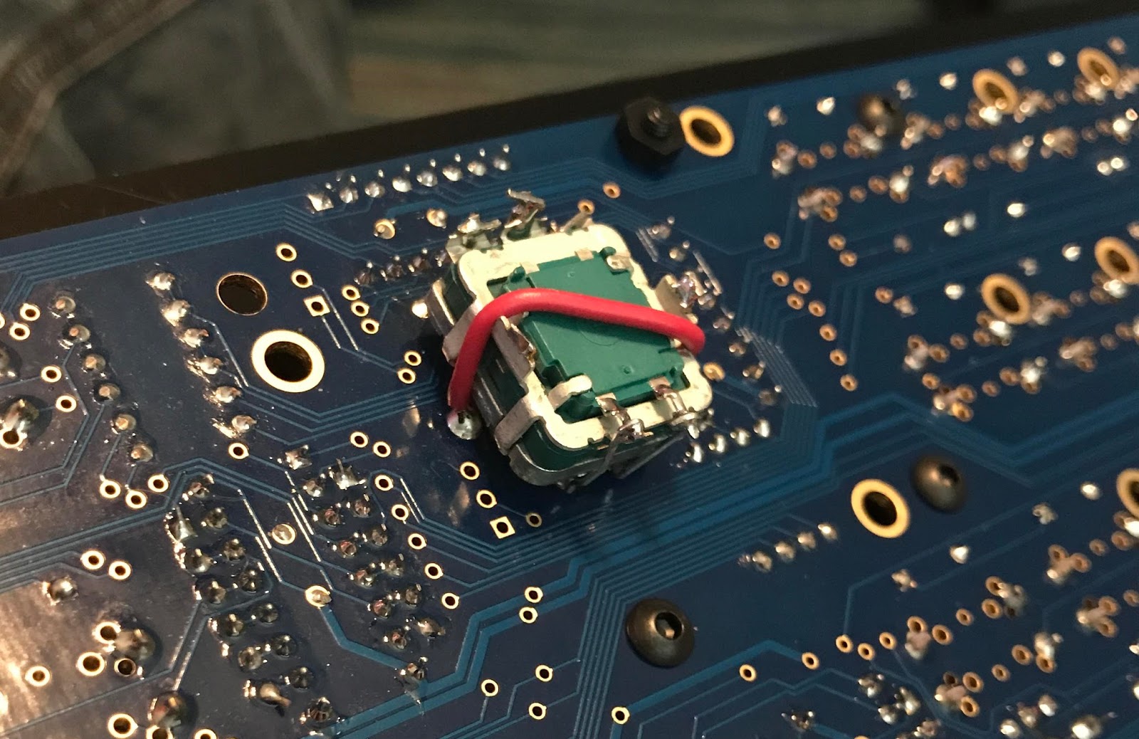
 NOTE: MISTAKE #2 - I realized once I received my prototype case and data wheel that I should have mounted the encoder UNDERNEATH the PCB instead of soldering to the top-side like the other encoders! If you want to use a regular knob for your data encoder, then this isn't a problem. But I wanted to use the "jog/alpha/scrub wheel"-style knob like on my Waldorf MWxt! As I'm always in a rush to do things and couldn't settle for ordering a replacement encoder, I disassembled the installed encoder and desoldered it from the PCB. After reassembling, I found two nuts on some other pots I had laying around and mounted the encoder to the board using one nut as a spacer and one to secure the encoder in place. I added a short piece of insulated wire to help hold the encoder in place and together and added some clipped LED legs (removed from the bicolor LEDs which didn't need them) to connect the terminals back to the solder pads. Now the data wheel sits at a perfect height and still allows room for the push-button function.

 |
| Cliff K88/85 detail |
 |
| ALBS DK38 data wheel |
Finally, the knobs and data wheel that you choose are a matter of taste. Of course, they need to match the shaft style of the encoders you choose, knurled encoders won't accept a D-Shaft knob. For the 16 "general purpose" encoders, I used Cliff K88 Black D-shaft knobs with K85 black caps, but also got some grey caps for the quarter note steps if needed...all from TME in Poland, which had a great price and super fast shipping. I had them in Florida in 4 days with their standard shipping! A few other places in Europe carry them, but they either didn't ship to the US, charged too much for shipping, or didn't carry the right color or shaft type. Cliff in the US does not import this model, so no US distributors carry them. I also considered the "Small Soft (10mm)" Sifam knobs at Thonk.co.uk, and the ALPS knobs at Reichelt.de (who has MUCH better prices than US distributors, especially for IDC connectors and shrouded headers, for example...any European builder should consider ordering all their parts from them). Modular Addict now offers some knobs that might suit some builders (but I do not care for those). They also offer a data wheel (ALBS DK38) which I have chosen to use for my sequencer. It is taller than some others I've seen (like the one from Adafruit which is VERY short). You can find the Modular Addict option here. If you choose to order the DK38, I recommend the Bourns 20mm encoder with switch from my parts kit and that it be mounted as shown above, from the underside.
My Mouser kit for this module includes the rotary encoders (I used modified Bourns 20mm w/ switch for all encoders, but the kit now contains one 20mm w/s and sixteen 15mm w/s), the tact switches (E-Switch brand), switch caps (see additional part numbers below for some optional gray and red caps for the transport controls), a flat-top 5mm "Beat" LED, all caps, resistors and arrays, 3mm LEDs (single and bi-color), diodes, sockets, chips, and headers.....but again, no knobs or wheel. I figured that the selection of knob style should up to the individual builder. You'll need to select a 6mm D-shaft knob (preferably with no indicator mark), but the color, material, and shape is up to you. Likewise, the data wheel you choose should be for 6mm D-shaft, but the color and diameter is a matter of taste. Note that some data wheels will sit high on the shaft of these encoders, so some modification may be required or an encoder with a shaft of different length.

As suggested in Hawkeye's build guide, all the LEDs I used are bi-color, so I needed to remove one leg and bend the remaining two slightly to align with the panel. You can choose to do this too, but it is probably easier to order single color for those locations that don't require bi-color. Follow this datasheet for the bi-color LED for proper installation: http://www.mouser.com/ds/2/239/S_110_LTL1BEKVJNN-369643.pdf

I made my 2x5mm LED cutouts very tight, only about 0.1-0.2mm clearance, so I beveled the underside of the top panel around each LED hole using a Dremel-type rotary tool to help the LEDs realign properly when I have to remove and replace the panel. I would probably do this with a panel made for 3mm round LEDs as well using a drill press and an appropriate countersink for acrylic.
More Info : http://www.midibox.org/dokuwiki/doku.php?id=wilba_mb_seq
Purchase
Schematics/Images
Panel / Enclosure
 |
| Mongbox |
Forum member Mongrol designed an acrylic case called MONGBOX for the STM32F4-based SeqV4 and made the files available for others to use to make their own if they or someone they know have access to a laser cutter or if they want to order from a company like Ponoko. This is the design that I adapted to build my case, but there was an issue with the scale. See the "scale fixed" version of the file if you are using Inkscape. I advise that you have whoever will cut your case verify that the measurements are correct when they load the file on their machines! Neither Mongrol nor I assume responsibility for any mistakes!
Mongbox enclosure thread : http://midibox.org/forums/topic/20221-mongbox-enclosure/
Mongbox build thread : http://midibox.org/forums/topic/19900-mongrols-midiboxseqv4-build/
Mongbox files : https://github.com/mongrol/mongbox_enclosure
 |
| Original panel style |
The original MIDIBox SeqV4 used an older Core which did not have built-in USB, SD reader, etc, so this design does not work properly with an STM32F4-based V4, so you will need to modify the rear panel. Here's a link to a set of panels for that case style:
http://thebeast.co.uk/?product=midibox-mbseq-v4-desktop-enclosure-panel-set
 There are DXF and FPD files available on the Wiki page if you'd like to have aluminum panels made, either the 17" panels like used in "the beast" case above, or a 19" panel for use with a 3U rack case. Double check that the design has all the mounting holes you need for fastening to your case of choice.
Wiki page : http://www.midibox.org/dokuwiki/doku.php?id=wilba_mb_seq
There are DXF and FPD files available on the Wiki page if you'd like to have aluminum panels made, either the 17" panels like used in "the beast" case above, or a 19" panel for use with a 3U rack case. Double check that the design has all the mounting holes you need for fastening to your case of choice.
Wiki page : http://www.midibox.org/dokuwiki/doku.php?id=wilba_mb_seq
DXF Files : http://www.midibox.org/dokuwiki/lib/exe/fetch.php?media=wilba_mb_seq:wilba_mbseq_dxf.zip
FPD Files : http://www.midibox.org/dokuwiki/lib/exe/fetch.php?media=wilba_mb_seq:wilba_mbseq_fpd.zip
My Mongbox "Remix"
I made my own case based on the Mongbox design above, but I had to modify it quite a bit to accommodate all the modules I wanted to squeeze in. I had several prototypes cut from wood and acrylic. I made my "remix" of the Mongbox a bit bigger in two dimensions to fit my additional modules, moved things on the rear panel to accommodate those modules, and changed the front and rear panels so that the split panel moves to the front. This was necessary to mount all the modules side by side. I will make my fabrication files available when they are edited in case anyone else would like to copy my build or use it as a template.

Finally, search the forum for the latest posts about cases, enclosures, and panels if none of these suggestions fit your needs
The above sections cover the bare-bones SEQv4 build as described in the beginning of this post. The following sections cover the additional features/modules I included in my own SEQv4 build....
Quad_IIc_MIDI (4 Outs)
 |
| Shown without BLM and Aux DIN options installed |
As mentioned above, the Quad_IIc_MIDI board adds four more MIDI outputs as well as the BLM port and a place to mount another 5-pin DIN connector for DIN Sync (I’ve seen this described as an Input, but I’m not sure, need to find more info. Possibly not relevant with STM32F4 core).
I have put together a Mouser cart which you can order or just use as a reference. You may decide to search for a different DIN socket (the MIDI outs and DIN Sync socket are all the same part), but keep in mind that not all sockets are built the same. The all-black sockets I used (from DIGI-Key, as opposed to the silver-faced sockets in the Mouser cart) had a different measurement from face to front leg. This slight difference affects the spacing between the rear panel of the enclosure and the connector, but more importantly may interfere with the mounting hole locations on the bottom panel. If you plan to use my enclosure design, double check the hole pattern and make sure it matches for your selected socket, and also that the Quad_MIDI_IIc board will not interfere with the STM32F4 core location.
The 5-pin DIN socket is one of the parts that I found to have a wide range of costs depending on the distributor, from $1/each to $4/each! The BLM/Sync section of the PCB could actually be cut off and separated from the MIDI port section as the circuits are fully independent, but the mounting holes on the PCB aren’t designed for this, you may need to modify. In my case design, the power switch and DC input are inline with where the BLM and Sync sockets would be making those features unusable, but do not require the PCB to be modified.
Note***: My Mouser cart contains the four 16F88 chips needed to build this module however they are NOT PREPROGRAMMED! You will need to program them yourself, OR omit them from the order and buy them preprogrammed from a member of the forum (that's what I did).
I have included both a SIL 4-pin male header as well as a 5-pin male header and two 10-pin female IDC connectors for connecting the Quad_IIc to the core, but you can omit these if you prefer a SIL connector like shown in the top sections of this page. There are only four holes on the PCB for this header, so to assist in proper connection, I used a 5-pin header and cut off one leg on the bottom of the header and offset the dummy pin so that the female connector aligns correctly. (next time I disassemble my SEQv4, I will add a photo here)
The Quad IIc_MIDI PCB is $9, and my full Mouser cart is $40.50. Actually, the kit is not quite full: it does not include a 5-Pin DIN socket or SIL 3-Pin male for the Aux DIN Sync because I cannot explain how this is implemented. If this is something you want from the Quad_IIc, you should research this feature on the forum before ordering a kit so you can add these parts. If you don't plan to populate and use the BLM expansion part of the board, you can order the parts kit with the suffix "-no BLM" ($36.50)
( see parts list below):
Purchase
Schematic/Dimensions/Image/Parts List
Quick View - http://www.midibox-shop.com/images/quad_IIcMIDI_QV.gif
Schematic - http://www.midibox-shop.com/images/quad_IIcMIDI_schem.pdf
Parts List from MIDIBOX Shop:
| IC1x  | IC-Socket for 16F88                |  4  |
| LEDx  | 3mm LED red                        |  4  |
| Q1x   | 20mhz crystal                      |  4  |
| C3    | 10µF Electrolytic capacitor        |  1  |
|C1x,C2x| 15pF Ceramic capacitor "33"        |  8  |
| C4x   | 100nF=.1µF Ceramic capacitor "104" |  4  |
| R2x   | 220Ω resistor                      |  4  |
| R9x   | 220Ω resistor                      |  4  |
| R10x  | 220Ω resistor                      |  4  |
| --    | 5 pin DIN connector                |  4  |
| J4    | 1x4 pinheader                      |  1  |
|-------|---optional BLM connection parts----|-----|
| IC2   | 6N138 optocoupler                  |  1  |
| IC2   | IC-Socket for 6N138                |  1  |
| R6    | 1KΩ resistor                       |  1  |
| R7    | 4.7KΩ resistor                     |  1  |
|R8-R10 | 220Ω resistor                      |  3  |
| D1    | 1N4148 diode                       |  1  |
| --    | 8 pin DIN connector                |  1  |
| --    | Box Header 2x5                     |  1  |
Dimensions: 135mm x 46mm
Line Driver (transmit/receive)
The Line Driver is the module used to buffer signals sent from the MIDIBox Seq enclosure to a breakout box or auxiliary panel which typically contains the analog outputs for CVs, gates, triggers, and clocks. If your build does not require an external expansion box, or if you are building your CV/Gate outs and Core into the same enclosure, then you probably won't need the Line Driver. It may have some uses in other custom applications, but if you are just making a sequencer with MIDI in/out, you can probably do without it.
This module actually consists of two parts: a transmitter PCB and a receiver PCB, or Tx and Rx. Unfortunately, neither is available to order from the Modular Addict (at time of writing, doesn't hurt to check back there) nor Mike's, so you'll either have to get them fabricated or find some for sale on the Forum's Flea-market. The Tx board mounts inside the Seq enclosure and the Rx board mounts in your breakout box or aux panel. The Line Driver allows the two to be connected using a 25-pin serial cable with length up to "5M at 1Mbit/s", maybe even longer, according to uCapps site. Perhaps if you build the CV/Gate expansions into the same enclosure as your SeqV4, you may not need the Line Driver as the connections would be comparatively short. Search the Forum for answers to this if you prefer to build an all-inclusive device.
I had my Tx and Rx boards made at OSH Park as recommended on the uCApps page. The awkward part is that OSH Park requires you to accept and pay for three copies of any board you order. If you have them fabricated there, you end up paying almost $50US and receive 6 PCBs (I still have two extra sets from when I ordered my boards). So check the Flea-market first to see if anyone already ordered and have extras to sell, and if you end up having to order from OSH, you can offer your extras for sale there (or give/sell them to your friends when they start their OWN SeqV4 build), or you could organize a group-buy on the forum.
Images that depict different hardware configurations and how to connect them are shown on the uCApps site, but if you are building the SeqV4 and using the Line Driver Boards to add an analog expansion, you'll probably just need to see this one :
http://www.ucapps.de/mbhp/mbhp_line_driver_usecase_mbseq.png
Full page : http://www.ucapps.de/mbhp_line_driver.html
The files you need for fabrication are available on the uCApps page (also linked below), but I've also uploaded the .BRD files and shared the project at OSH Park to save you the trouble, and those are linked below under "Purchase"
Purchase
OSH Park: https://oshpark.com/
 |
| Transmitter PCB |
|
| Receiver PCB |
Schematics/Images/Files/Parts List
Tx Image : http://www.ucapps.de/mbhp/mbhp_line_driver_transmitter_v1.png
Rx Image : http://www.ucapps.de/mbhp/mbhp_line_driver_receiver_v1.png
Tx Schematic : http://www.ucapps.de/mbhp/mbhp_line_driver_transmitter.pdf
Rx Schematic : http://www.ucapps.de/mbhp/mbhp_line_driver_receiver.pdf
Tx .BRD File : http://www.ucapps.de/mbhp/mbhp_line_driver_transmitter_v1.brd
Rx .BRD File : http://www.ucapps.de/mbhp/mbhp_line_driver_receiver_v1.brd
Ucapps Parts List : http://www.ucapps.de/mbhp/mbhp_line_driver_orderlist.txt
AOUT_NG (CV Outputs)
In order to add control voltage (or CV) outputs to the MIDIBox SeqV4, you will need to add one of the three AOUT modules (analog out). These are the AOUT, the AOUT_NG (no gates?), and the AOUT_LC (low cost?).
- AOUT provides eight 12-bit CV outputs and two gate outputs
- AOUT_NG provides eight 12-bit CV outputs with bi-polar option, no gates
- AOUT_LC provides two CV outputs at either 12/4-bit or both at 8-bit
For a well worded comparison and more information, see the AOUT_NG wiki page here :
http://www.midibox.org/dokuwiki/aout_ng
 I opted to build the AOUT_NG to start with, but if I find that the precision is not accurate enough for my taste, I will switch to the AOUT module instead.
The AOUT_NG requires a bipolar power supply to provide +/-12VDC, and since the Line Driver Rx only provides +5VDC, I needed to include an additional power source in my build. If you build your expansion as a Euro-rack module, you can use your rack for power if you have spare amperage. I build a MFOS Wall Wart Supply, but I'll discuss that more when I post about the Breakout Box (Note: the AOUT and DOUT boards are not mounted inside the Mongbox Remix enclosure. You will need to add a second enclosure or design a case to support your desired hardware combination).
 Note : You may want to leave the SIL 5-pin and SIL 3-pin male headers unpopulated until you decide what connectors to use. I ended up using a flying Male/Female connector for J1 and a pre-assembled locking connector for J3 which I ordered from allelectronics.com. I left off J2 and J4 completely as J2 was in the way of my power switch and AC inlet and J4 has no current application (see image above).

I've also designed and had fabricated some additional PCBs: some for mounting the output sockets and IDC headers for connecting to the AOUT_NG boards and some to connect the Bipolar Option switches to the option headers (so there will be no hand-wiring).
The AOUT_NG PCB costs $9, and there are two parts kits I have assembled at Mouser. One kit includes all the necessary parts including those for the bipolar option ($66, includes two 16pin female IDC connectors which you may not need), and one kit includes everything except the bipolar option parts. If you don't require the bi-polar option and/or want to source the parts yourself, see the wiki page below for what parts can be removed from the order. Also, you may choose to add a set of switches instead of the shunts/jumpers if you do install the bi-polar option so you can toggle between both modes for each output. I did not include these switches in either kit, but the part number for the switches and caps I used in my Breakout Box are linked below. If you are REALLY sure that you will ALWAYS or NEVER want the bipolar option for each output and want to save about $4, you can omit two 16 pin male headers and the shunts from the kits and just bridge across the relevant solder pads with spare wire or a cut-off resistor leg. See wiki page below for correct jumper/bridge orientation.
http://www.midibox.org/dokuwiki/aout_ng
Purchase
My Mouser Kit with Bipolar option: https://www.mouser.com/ProjectManager/ProjectDetail.aspx?AccessID=284b61f2ef
My Mouser Kit WITHOUT Bipolar option: https://www.mouser.com/ProjectManager/ProjectDetail.aspx?AccessID=c4f557cb8b
Schematics/Images/Files/Parts List
Quick View Image : http://www.midibox.org/dokuwiki/lib/exe/fetch.php?w=100&tok=cec3ae&media=seppoman:aout_ng.gif
Schematic : http://www.midibox.org/dokuwiki/lib/exe/fetch.php?media=seppoman:mbhp_aout_ng_r1_schematic.pdf
Eagle Layout and Schematic : http://www.midibox.org/dokuwiki/lib/exe/fetch.php?media=mbhp_aout_ng_r1.zip
Parts List : http://www.midibox.org/dokuwiki/aout_ng#parts_list
DOUT (Gate/Trig/Clock)
The DOUT module (also referred to as DOUTX4 and DOUT_R5) is the digital output expansion for MBHP, and can be used for a variety of applications. With a MIDIBox SeqV4, it is typically used to send gate, trigger, and clock signals to analog equipment like synthesizers and drum machines. "Digital" in this instance means that there are two states to the signal: high and low, on and off, 5V and 0V, as examples. The suffix "X4" indicates that there are 4 separate shift registers, each providing 8 outputs, so a single DOUT board can deliver 32 outputs. Modules may be daisy-chained to add more outputs, or you can choose not to populate the entire board if you only require 8/16/24 outputs.
I used individual resistors rather than the resistor array ICs. As with the AOUT_NG, I fabricated output PCBs for my breakout box/panel so I don't have to do any point-to-point wiring. These include LEDs and LED driver circuits for each output.
http://www.ucapps.de/mbhp_dout.html
Shift registers are assigned in the hardware config file stored on the SD card. An example of the required edits to the config file can be found at the bottom of the Hardware Options page (note that there is a typo which refers to SR7 instead of SR6)
Purchcase
Board only : https://modularaddict.com/manufacturer/midibox/midibox-dout-pcb
My Mouser Kit : https://www.mouser.com/ProjectManager/ProjectDetail.aspx?AccessID=deb19a45b2
Schematics/Images/Files/Parts List
Parts List : http://www.ucapps.de/mbhp/mbhp_doutx4_r5_orderlist.txt
Schematic : http://www.ucapps.de/mbhp/mbhp_doutx4_r5.pdf
Dual-Layer Image : http://www.midibox-shop.com/images/dout/DOUT_R5qv.gif
PCB Image : http://www.ucapps.de/mbhp/mbhp_dout_r5_detail.jpg
TPD

The Track Position Display module, or TPD, was sort of an afterthought for me with regards to my build. I did not design my SEQv4 and Breakout enclosures to accommodate this module, so some modifications to their designs were required along with a separate enclosure for the TPD itself. There is also the option to use the Eurorack version of the TPD PCB and build the unit into a Euro faceplate (I chose not to build my TPD and Breakout as Euro modules because I have more analog gear than just my modular, and the modular is not easily portable). I might redesign a breakout box which includes the AOUT/DOUT options and the TPD in one, or an even larger case for all modules together... but for now, my build will consist of three separate but interdependent boxes.
The TPD adds several features to the build. The name "Track Position Display" refers to the 16x8 LED matrix which shows the relative progress of each track's cycle within the selected patterns. There is an encoder to adjust the sequencer's internal tempo and a four-digit display to continually indicate the current BPM. A three-digit display shows a step counter. Finally, there are four assignable buttons labeled I-IV (which can be thought of like buttons F1-F4 on Wilba's CS Board) and four bicolor LEDs, and these are programmable by editing the configuration file using MIOS Studio.
As an example, I have assigned Red LED I to flash at the start of each measure, Button II and its Red LED to Tap Tempo, Button I and its Green LED to FX Menu, Button III and its Green LED to Track Length Menu, and Button IV and its Green LED to Track Direction Menu. I can always change these easily by editing the config file and saving to the SD Card via the USB connection.
I bought the PCB and parts kit from ilmenator on the MIDIBox forum. You'll need to register and message him to order boards and kits. More information can be found on the wiki page. Here you will a build guide, BOM (if sourcing parts yourself), the pin allocations for the assignable buttons and LEDs, schematics, PCB images, example config files, etc.
I will share the design for the pictured enclosure in another post!
 A basic how-to guide:
 A laser-cut acrylic (or other material) case is typically assembled using a "tab and slot" design which connects all sides of the enclosure keeping it square. You still need to fasten at least two opposite sides (the ones with slots) to keep the case from falling apart. I may have gone a bit overboard with my fasteners, a few more than in the original Mongbox, but I wanted to make sure my build was rigid and that pushing the buttons and encoders would cause minimal flex to the CS Board and the acrylic itself.
 SEQV4 Enclosure (Longback)
 This is equivalent to the main sequencer case I built for myself which includes STM32 Core, Wilba CS Board, power switch and inlet, one Quad_IIc_MIDI, two MIDI_IO, and a Line Driver Transmitter. I called this design the "Longback Remix" because the original Mongbox design's rear panel was made of two parts, and I needed to have a "longer", single-piece rear panel to fit all my MIDI ports. This case is taller and deeper than the original Mongbox, has some modified/additional graphics, and a different cut-out pattern. This design uses 2x5mm rectangular LEDs for all except the "Beat" LED. I will add another version of Longback with 3mm round LED holes. You will need to order a clear acrylic sheet for the LCD window, find that file below. Scroll down to see build guide.
 I built this external case to house and power my CV/Gate/Clock/Trig signals (AOUT_NG and DOUT modules). It connects to the main sequencer via a DB25 cable using the Line Driver Receiver port. There are two DIN Sync ports which are internally wired to the first two clock and start/stop signals. Power switch and inlet drive the AOUT_NG board via a MFOS Wall Wart PSU, the DOUT chain gets its power from the Line Driver. I had some PCBs fabricated for the outputs to minimize any point-to-point wiring necessary to assemble the box. I will add links to these PCB files if you want to use the same sockets. Otherwise, you will want to design your own PCBs accordingly. This case is the same height and depth as the Longback above, so pairs nicely side-by-side, but it is still rather cramped within. You can simplify the build and any custom PCBs by eliminating the LEDs and driver circuits.... but I wanted immediate and constant verification that the signals were active. This design does not give external access to the trimmers of the AOUT_NG, the top panel must be removed in order to recalibrate...so calibrate before fastening shut! Scroll down to see build guide.


 All hardware is M3 unless otherwise noted.
 Fitting - On the cases I've made so far, the holes for all the M3 fasteners on the top panel were counter-sunk (using the tool shown and a drill press with a digital depth reading) so the screw heads are flush with the acrylic. This isn't necessary however. If you are happy to use pan-head or cap-screws, you need not modify the fastener cutouts.
 Graphics - You'll notice that the lines and text on my acrylic cases are white. I did this using a Lacquer-Stik... I just rubbed it into the etch and then wiped off the excess using 90% isopropyl alcohol. It's a bit awkward getting the diluted paint out of the cutouts, so be careful when wiping the excess off. Make sure to keep the lacquer stik sealed up well between uses to prevent it drying out. Remove the paper from the surface of the acrylic before you fill the etch or you will have too much paint to wipe away easily.
  I'm not even sure where to begin! If you're here reading this, you must have some idea of what it's all about, so I don't want to repeat myself. As you can see by this photo, I managed to squeeze my Core, 8 MIDI outs, 4 MIDI ins, and a line driver transmitter into my enclosure...along with the control surface and LCDs...and there's still so much room for activities!
  I started with a few prototypes made out of laser-cut wood with the help of Sean Pendleton. I quite liked them! The etching/cutting burns the wood slightly, so text shows up without being filled with paint, and cuts have a sort of reverse-vignette appearance - I'm sure there's a word for it. My first attempt didn't turn out quite right because of a scaling issue when loading an SVG into Inkscape which was made in Illustrator. Mongro1 helped sort out that issue and uploaded a file named "mongbox_scale corrected". This is the file I built my Ponoko case from.
  Mounting Hardware -
  Ribbon Cables - If you began with my parts lists from my previous post, then you should have all the connectors and ribbon cable you need to assemble this enclosure. You can see that I labeled the ribbons in my case to make breakdown and rebuild easier. Remember to make the ribbons that connect to the LCDs and CS Board to the Core and Line Driver long enough so that you can remove the panel enough to connect/disconnect the headers. It is very important to align pin 1 of each connector on a ribbon and that the connector be on the appropriate side at each end to allow a manageable flow of ribbons between stand-offs. This will likely require a twist or two in some ribbons.

 You must also remove the USB Power jumper from the Core Board's J17. I suppose it is possible to add a switch to select between external power and USB power, but I would not toggle back and forth while powered. I would likely recess the switch so it could only be actuated deliberately.


 The sockets I used were Cliff Electronics CL1384, the same type used in Doepfer modules until they switched to Cliff's FC681375V. I already a had a large enough stock of CL1384 sockets on-hand, so I designed the boards to use these. I might redesign the output boards at some point to use the FC681375V or another perpendicular socket. That might save a few millimeters inside the enclosure and allow a wider selection of caps for the MFOS PSU, and the threads/nuts on the FC681375V (and even FC681375VH) are a smaller diameter than the CL1384 and might lead to a neater front panel. The CL1384 is also available with gold contacts as the CL13845G. Note that the 3mm acrylic used for this enclosure is the maximum thickness you should use with any of these Cliff sockets. With the CL1384 sockets used in my case, the nuts rest slightly higher that the mouth of the socket, so a jack with a wide and flat diameter may not fully insert.


 There are quite a few ribbon cables crammed in here. We've got three 16-wire connectors for the AOUT_NG, one 10-wire connector for power to the LED drivers, and four 10-wire connectors for the DOUT shift registers (one of which continues on to the DIN Sync board).
  I made a mistake on the layout of the first DIN Sync board, but used it anyway in my personal case. I corrected the error by twisting 8 of the ribbon's wires just before the connector (see photo). I have corrected the error on the board design (and removed the diodes you might notice is some pics here) and will share that fabrication file if anyone wants to include the DIN Sync outs.
  The DOUT shift registers are shown sequentially from right to left in this image, so you might consider its layout to be upside down compared to the top panel layout. It is important to edit the config file appropriately. With my top panel layout and the DOUT's orientation, you would make the Clock outputs SR n, the second set of Trigger outs SR n+1, the first set of Trigger outs SR n+2, and the Gate outs SR n+3. See my own config file if using my same hardware options.
  The Line Driver Receiver, DOUT, LED drivers, and part of the AOUT_NG are all powered via the +5V on the DB-25 cable attached to the SEQv4 enclosure. However, the AOUT_NG also requires -/+12VDC which is provided by the MFOS Wallwart PSU. The MFOS is powered by an AMIGO 12VAC/1200mA supply, model AM-121200A. The power inlet and switch are the same used in my Longback enclosure.


